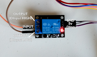
These power relays are great for simple control of turning power on and off to a device. The tricky part is finding any information on exactly how the pin mapping is setup.
From my own experimentation, the following is what I have observed.
If the INPUT voltage is 5V for example, by default that 5V will be sent to OUTPUT1. If a voltage is applied across VCC and GND, then the INPUT will be routed to OUTPUT2.
Wiring the VCC to a digital pin on the arduino can allow this to act as a digitally controlled switch.
Note that the pinout on this guy does not fit well on any breadboard (primarily because of the INPUT pin). Better to get one with a board.
When using the breakout board, i feel like the signal grouping is non intuitive based on the way the original relay pinout is laid out.


No comments:
Post a Comment